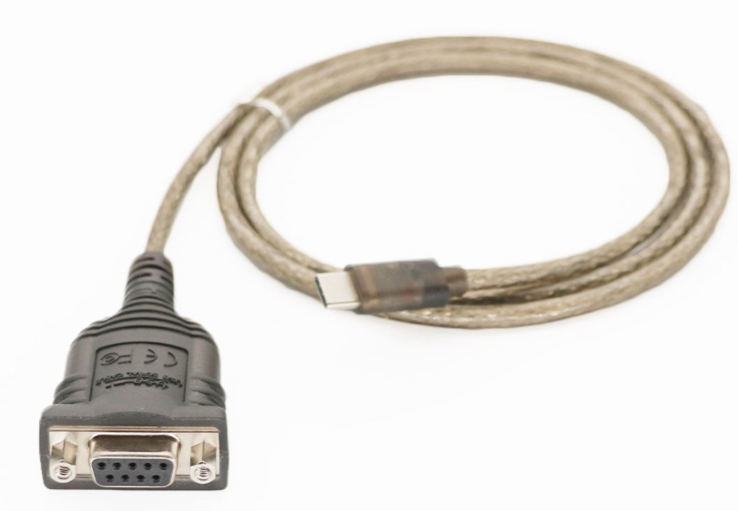
Es gibt zwei Möglichkeiten eine serielle Schnittstelle am Raspberry Pi einzurichten: Entweder
über den GPIO-Stecker oder mit einem externen USB-Seriell-Adapter. Da das Raspbian
Betriebssystem die gängigsten USB-to-Serial Adapter (z. B. den U232-P9) unterstützt, ist es
empfehlenswert, externe RS232-Geräte über USB anzuschliessen. (USB-to-Serial Adapter
finden Sie auf eBay oder in Computershops.)
Es gibt aber auch Zusatzgeräte, die man direkt am GPIO-Stecker aufsteckt und welche die
serielle Kommunikation über das GPIO verwenden. Dazu gehören die meisten GPS- und GSM-
Geräte, die speziell für den Raspberry Pi entwickelt wurden. In diesem Fall werden für den
RS232-Datentransfer die GPIO Pins #8 und #10 (UART-TXD0 bzw. UART-RXD0) verwendet.
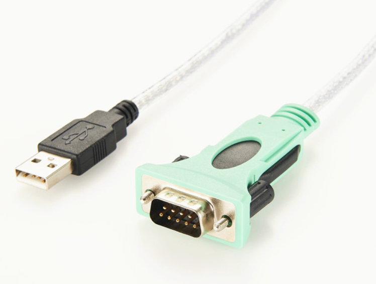
Standardmässig wird der serielle GPIO-Port für ein externes RS232-Terminal (bzw. einen
Terminal-Emulator) als Linux-Shell verwendet.
Dies ist eine interessante Alternative, um mit
dem Raspberry Pi zu arbeiten und erinnert etwas an die "guten alten Zeiten", als Terminals
(und Fernschreiber) die üblichen Ein-/Ausgabegeräte für Minicomputer und Mainframes waren.
Heute gibt es zwar keine dedizierten Terminal mehr, dafür aber virtuelle Terminals (Terminal-
Emulatoren) für alle gängigen Plattformen. Eines der beliebtesten Programme ist PuTTY, das
mit folgender Kommandozeile auch auf dem Raspberry Pi installiert werden kann:
sudo apt-get install putty
Nach der Installation gibt es eine Startikone im Menü unter Internet.
Wählen Sie No bei bei login shell:
Serielle Schnittstelle des GPIO mit dem Raspberry Pi 3
Die serielle Kommunikation funktioniert leider mit der aktuellen Version des Jessie-
Betriebssystem für den Raspberry Pi 3 anders als mit den Vorgängermodellen. Erstens wir der
Name ttyAMA0, der bisher für die serielle Kommunikation mit dem GPIO reserviert war, neu
durch den Bluetooth-Treiber beschlagnahmt. Der serielle GPIO-Port heisst neu ttyS0. Zweitens
und ärgerlicher ist die Tatsache, dass die serielle Schnittstelle aufgrund der höheren CPU-Core-
Taktfrequenz des Raspberry Pi 3 nicht mehr funktioniert. Damit die Baudraten stimmen,
müssen Sie die Taktfrequenz anpassen.
Obwohl für den Datenaustausch zwischen einem Computer und Peripheriegeräten meist
Bluetooth, Ethernet oder USB-Schnittstellen und bei Mikrocontroller-Systemen I 2 C, SPI und 1-
Wire verwendet werden, ist die Kommunikation über die serielle Schnittstelle (RS-232C) immer
noch beliebt.
Traditionsgemäss wird die serielle Schnittstelle oft zur Kommunikation mit
Messeinrichtungen (Voltmeter, Oszilloskopen, usw.) verwendet, aber auch, um mit Modems,
Roboter, oder Mikroprozessor-Systemen zu kommunizieren (z.B. Programmdownload auf den
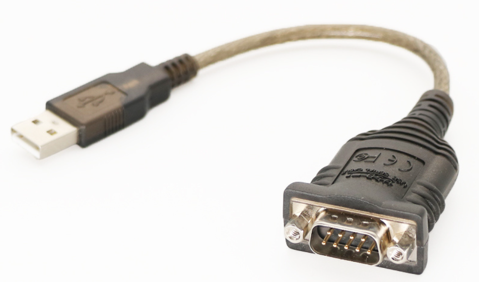
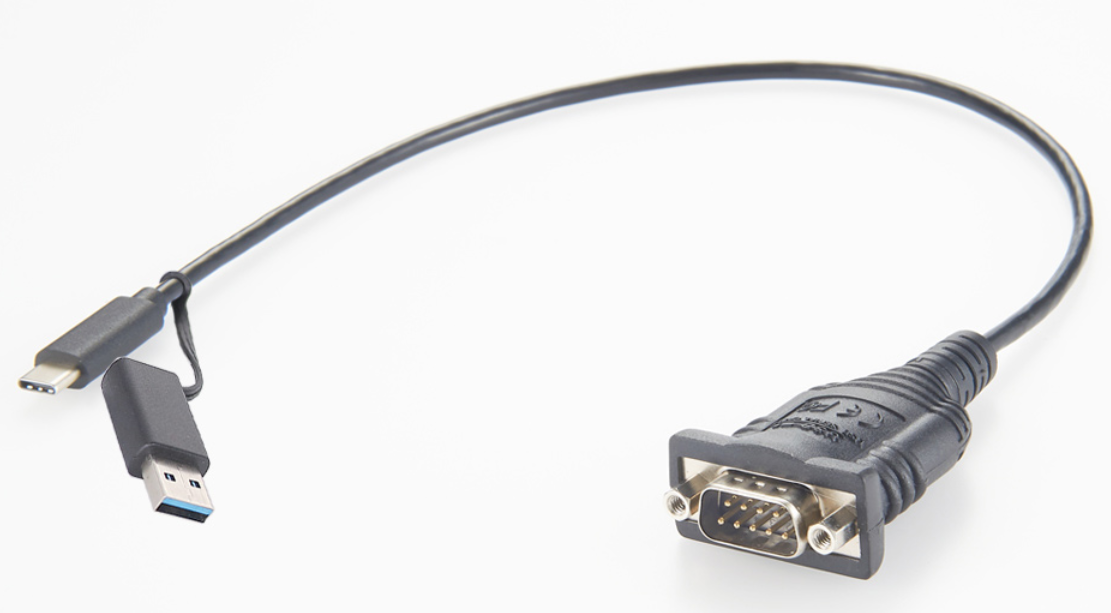
Arduino). Moderne Computer haben keine seriellen Ports mehr, jedoch kann dieses Problem
leicht mit einem billigen USB-Seriell-Adapter gelöst werden.
Die Struktur der übertragenen Daten ist einfach. Die Datenbytes werden über eine einzige
Leitung sequentiell übertragen. Der Datentransfer beginnt mit einem Startbit, durch welches
dem Empfänger die Datenübertragung angekündigt wird. Dann folgen die Daten mit 5, 6, 7
oder (normalerweise) 8 Bits. Um eine Fehlerkorrektur zu erleichtern, kann ein Paritätsbit
folgen, das angibt, ob die Anzahl gesetzter Bits ungerade oder eine gerade ist. Das Paritybit
kann aber auch fehlen. Der Transfer wird mit einem oder zwei Stopp-Bits abgeschlossen. Die
Sende- und Empfangsgeräte sind ausserhalb der Datenübertragung nicht miteinander
synchronisiert, das heisst, die Datenübertragung kann zu jedem beliebigen Zeitpunkt beginnen
(asynchrones Protokoll).
Es ist jedoch notwendig, dass die Zeitdauer für das Senden eines
einzelnen Bits für beide Geräte übereinstimmt. Diese wird durch die Baudrate (in Baud, Bits/s)
angegeben, und hat meist einen der standardisierten Werte 300, 600, 1200, 2400, 4800, 9600,
19200, 38400, 57600, 115200 Baud. Darüber hinaus können beide Geräte mit einem
Handshake (Flusskontrolle) bestätigen, dass sie für die Datenübertragung bereit sind. Man
unterscheidet zwischen Hardware- oder Software-Handshake, je nachdem ob für das
Handshake spezifische Handshake-Leitungen verwendet werden oder ob spezielle ASCII-
Zeichen (XON / XOFF) im Datenstrom eingebettet sind.
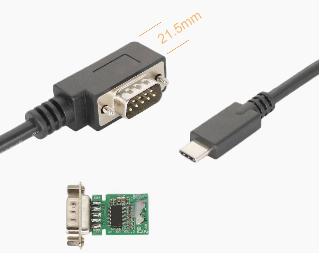
Eine typische RS232-Portkonfiguration umfasst daher: Baudrate, Anzahl Datenbits (5, 6, 7, 8),
Anzahl Stopp-Bits (1 oder 2), Parität (keine, ungerade oder gerade), Handshake (kein,
Hardware oder Software).
Beispiel: Der Spannungsverlauf während der Übertragung des Buchstaben 'B', mit der
Konfiguration: 7 Datenbits / keine Parität / 1 Stoppbit sieht wie folgt aus:
What is Auxiliary power unit APU ?
Auxiliary power unit
Auxiliary power unit Cable
Auxiliary Power Unit APU Cable
Auxiliary Power Connector Cable
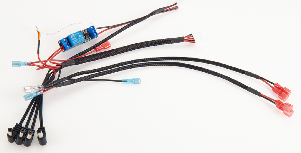
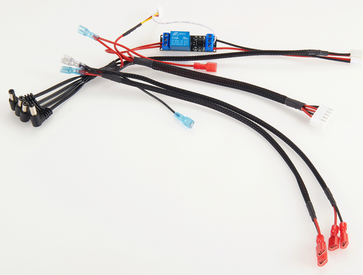
An auxiliary power unit (APU) is a device on a vehicle that provides energy for functions other than propulsion.
They are commonly found on large aircraft and naval ships as well as some large land vehicles.
Aircraft APUs generally produce 115 V AC voltage at 400 Hz (rather than 50/60 Hz in mains supply), to run the electrical systems of the aircraft; others can produce 28 V DC voltage .
APUs can provide power through single or three-phase systems.
As mechanical startup APU for jet engines
The first German jet engines built during the Second World War used a mechanical APU starting system designed by the German engineer Norbert Riedel.
It consisted of a 10 horsepower (7.5 kW) two-stroke flat engine, which for the Junkers Jumo 004 design was hidden in the intake diverter, essentially functioning as a pioneering example of an auxiliary power unit for starting a jet engine.
A hole in the extreme nose of the diverter contained a manual pull-handle which started the piston engine, which in turn rotated the compressor.
Two spark plug access ports existed in the Jumo 004's intake diverter to service the Riedel unit's cylinders in situ, for maintenance purposes.
Two small "premix" tanks for the Riedel's petrol/oil fuel were fitted in the annular intake.
The engine was considered an extreme short stroke (bore / stroke: 70 mm / 35 mm = 2:1) design so it could fit within the intake diverter of jet engines like the Jumo 004.
For reduction it had an integrated planetary gear.
It was produced by Victoria in Nuremberg and served as a mechanical APU-style starter for all three German jet engine designs to have made it to at least the prototype stage before May 1945: the Junkers Jumo 004, the BMW 003 (which uniquely appears to use an electric starter for the Riedel APU),[7] and the prototypes (19 built) of the more advanced Heinkel HeS 011 engine, which mounted it just above the intake passage in the Heinkel-crafted sheetmetal of the engine nacelle nose.[8]
The Boeing 727 in 1963 was the first jetliner to feature a gas turbine APU, allowing it to operate at smaller airports, independent from ground facilities. The APU can be identified on many modern airliners by an exhaust pipe at the aircraft's tail.[9]
USB 3, USB 4, Thunderbolt, & USB-C — everything you need to know ?
USB 4.0 is described as the next generation of USB. Announced in 2019, it promises to provide significantly faster transfer speeds, better port usage, and the ability to provide tunneling of display ports and PCIe to external devices.
USB 4.0 utilizes a single standard connector (USB-C) and brings multiple connectivity standards together. USB 4.0 also ensures backward compatibility with almost all previous standard inputs, including USB 3.0 and USB 2.0.
USB4 is a USB system specified in the USB4 specification which was released in version 1.0 on 29 August 2019 by USB Implementers Forum
In contrast to prior USB protocol standards, USB4 requires USB-C connectors, and for power delivery, it requires support of USB PD. In contrast to USB 3.2, it allows tunneling of DisplayPort and PCI Express. The architecture defines a method to share a single high-speed link with multiple end device types dynamically that best serves the transfer of data by type and application. USB4 products must support 20 Gbit/s throughput and can support 40 Gbit/s throughput, but due to tunneling even nominal 20 Gbit/s can result[citation needed] in higher effective data rates in USB4, compared to USB 3.2, when sending mixed data.
The USB4 specification is based on the Thunderbolt 3 protocol specification.[2] Support of interoperability with Thunderbolt 3 products is optional for USB4 hosts and USB4 peripheral devices, and is required for USB4 hubs on their downward facing ports and for USB4-based docks on their downward and upward facing ports.
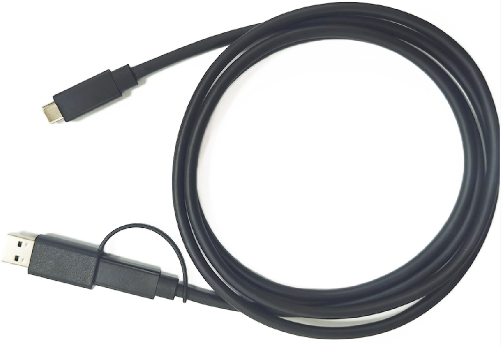
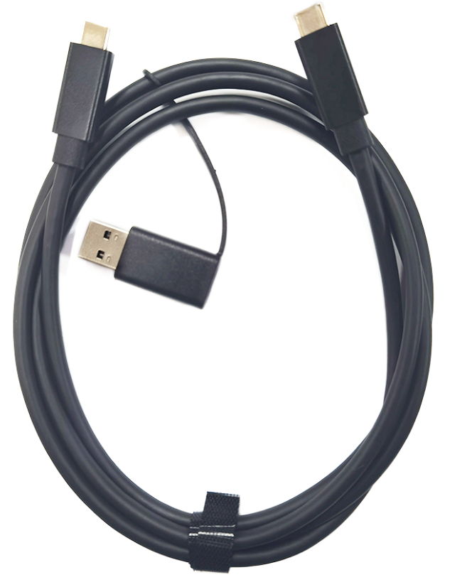
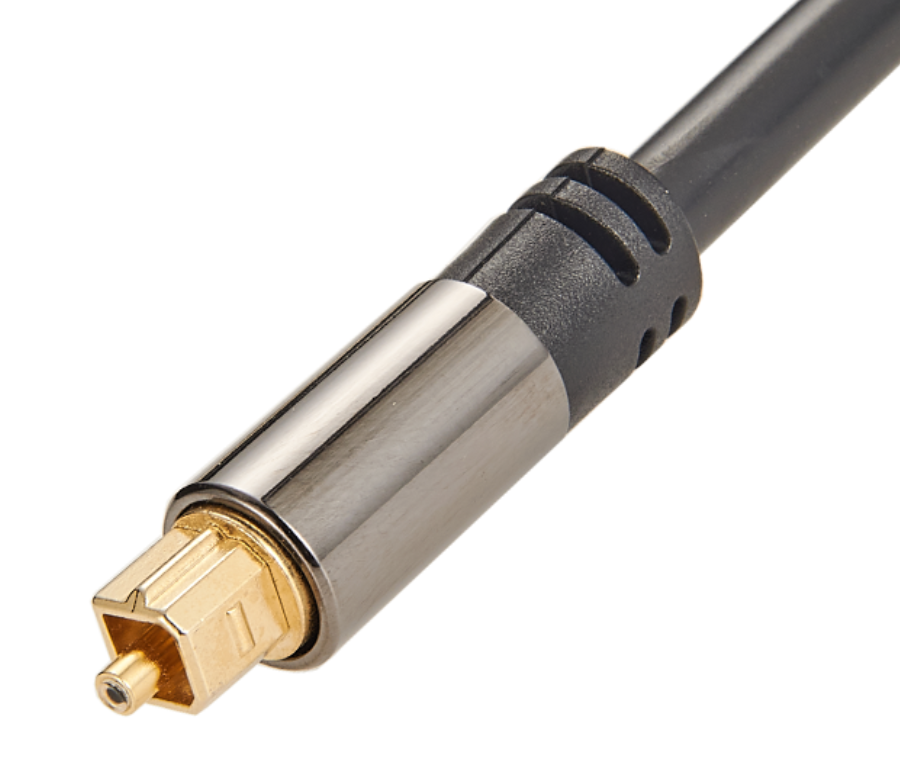
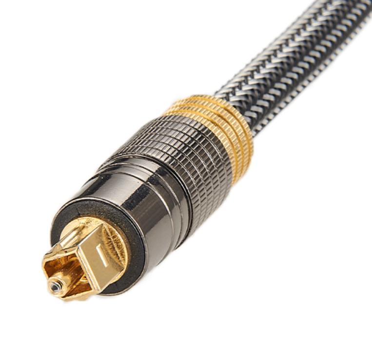
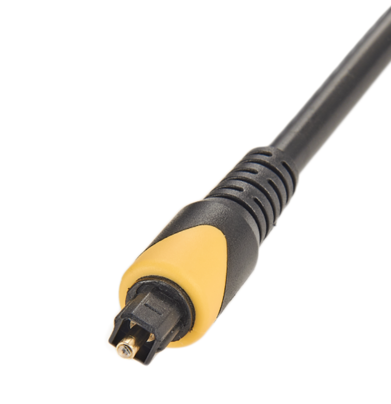
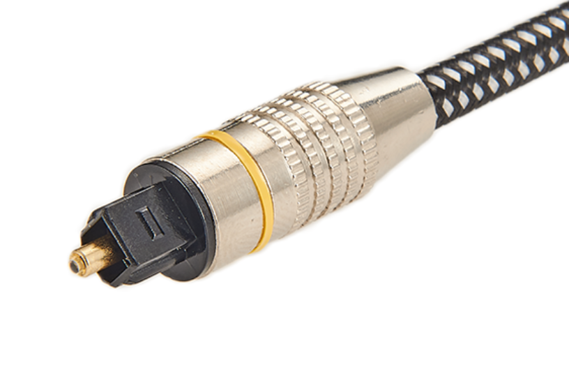
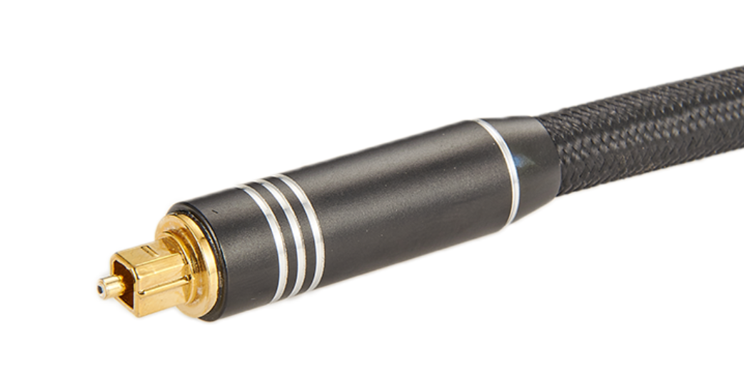
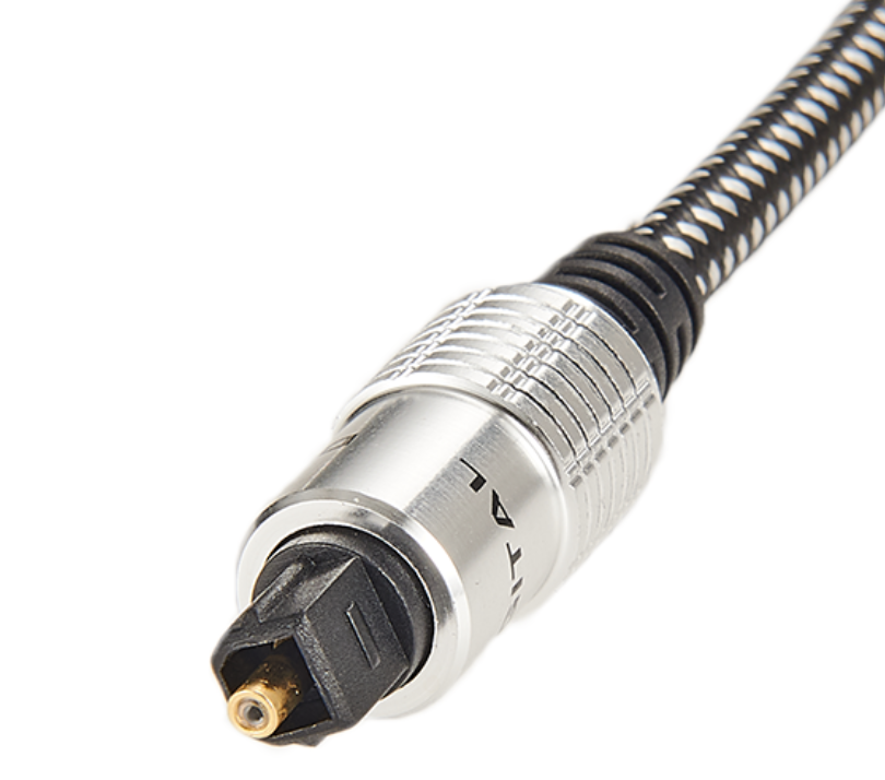
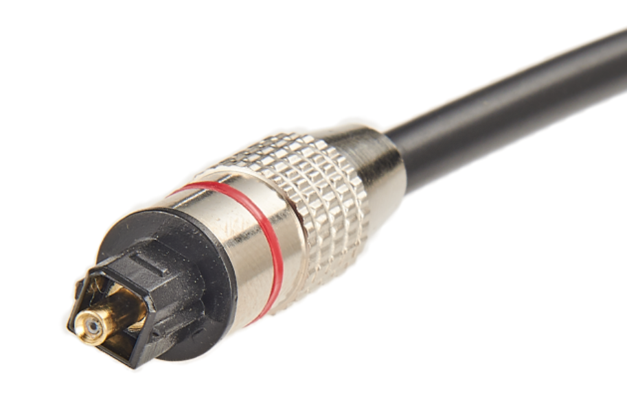
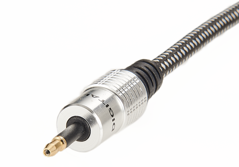
TOSLINK cables (also called optical digital cables) convey digital signals in the S/PDIF format from computers and audio sources to other pieces of consumer audio equipment. TOSLINK is an older digital standard which uses pulses of light traveling down a fiber optic cable to represent digital ones and zeroes. Due to the information being encoded via light instead of electrons on/in a wire, TOSLINK is immune to RF or EMF interference.
In theory, TOSLINK conveys digital data perfectly, and any cable will do the job. However, issues such as cable reflectivity, and fiber optic cable type (glass vs plastic) and diameter may have an effect on the timing of the signals. In other words, do the pulses reach their destination in the exact same spacing and timing as they were sent. Any discrepancies can cause a phenomenon known as jitter which can create a "smearing" of the sound. However, please do note that many of us cannot hear the differences, and doing so requires an audio system with very high resolution. But if you have an audiophile-grade system, buying a better quality TOSLINK cable will not be a huge expenditure to you. We judged our picks for best TOSLINK cable based on construction, durability, price, and overall design.
For more information on what to look at in selecting the best optical cable in 2021, We have listed below the optical cables available for you to help you decide what product is best to buy.
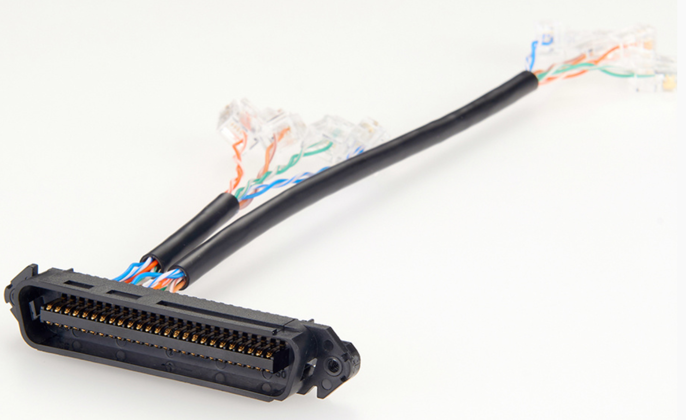
Console cables — also known as Cisco cables, rollover cables and management cables — are designed for a specific purpose. They connect Cisco networking devices to terminals or PCs for configuration. Typically, the Cisco end will connect via RJ45, and the terminal end will conclude in a serial connection.What matters most about console cables is the specific nature of the connection. This is not an Ethernet or networking connection. It is a terminal connection, and its purpose is to enable the connected computer to configure the networking device. This is true for older Cisco equipment and brand-new devices. Configuration is performed through the serial connection.What Are the Primary Kinds of Console Cables?Console cables come in many shapes and sizes and with a variety of connector types. There are three that are used more commonly than the rest, mostly because of the frequency with which you will see these different connectors.
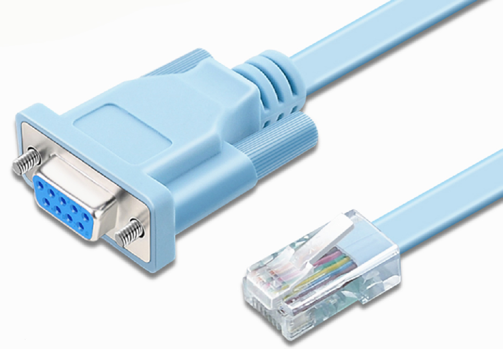
A RJ45 to DB9 is probably the most well-known console cable today. Once upon a time, console cables were connected with improvised “kits” that were little more than a string of adapters on the end of a serial cable. Today, you can get an RJ45 to DB9 cable that replaces the “kit” with a single cord. As the name implies, one end is RJ45 and the other is DB9.
This is the most direct serial connection available, and it comes packaged with a wide variety of Cisco devices. It’s something of a standard, but despite that, it’s designed to communicate with terminals that have the DB9 port. If you want to connect it to a PC or laptop, you’ll likely need an additional adapter between the DB9 end and your USB port.
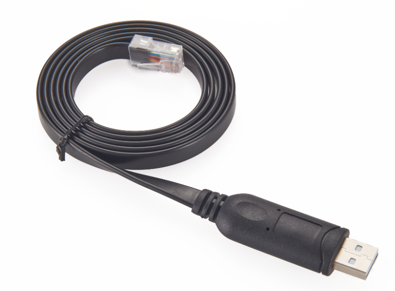
Another common console cable, the CAB-CONSOLE-USB, connects the USB on a terminal to a mini-B port on the Cisco device. You’ll notice the lack of RJ45 connectors. This is a specialized cable that services smaller, often portable devices. Despite the connection pieces, this is still a "serial" cable that enables terminal communication.
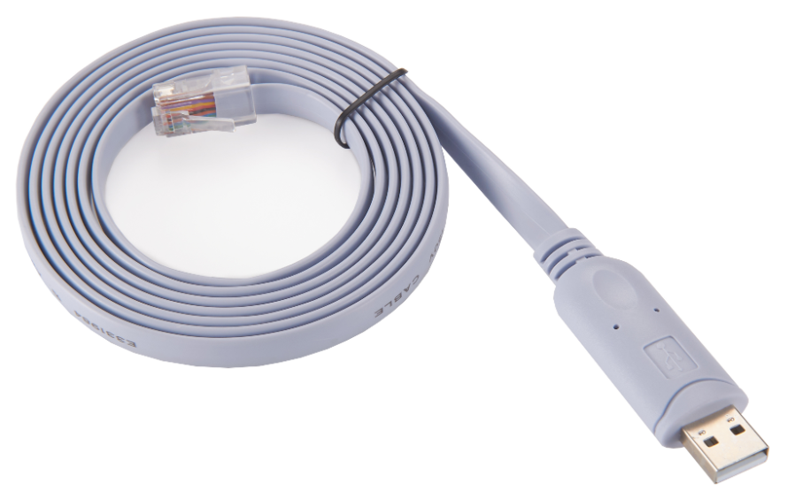
The CAB-CONSOLE-USB-RJ45 is arguably the most modern console cable. It ditches the less-used DB9 connector and streamlines your communication. It goes seamlessly from the console port on the Cisco device to a standard USB port on a PC. It’s the simplest way to create a terminal connection with modern equipment, and it is not a standard inclusion in Cisco hardware packages. A handful of these cables can make network control substantially faster and easier.
That is what you need to know about console cables. In the past, networking staff had to waste valuable time finding creative ways to bridge connections and configure devices. With modern console cables, that time is saved and networking is that much easier.
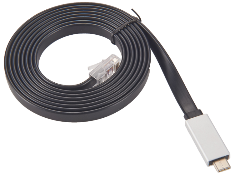
Raspberry Pi (/paɪ/) is a series of small single-board computers developed in the United Kingdom by the Raspberry Pi Foundation in association with BroadcomThe Raspberry Pi project originally leaned towards the promotion of teaching basic computer science in schools and in developing countries.The original model became more popular than anticipated, selling outside its target market for uses such as robotics. It is widely used in many areas, such as for weather monitoring, because of its low cost, modularity, and open design. It is typically used by computer and electronic hobbyists, due to its adoption of HDMI and USB devices.After the release of the second board type, the Raspberry Pi Foundation set up a new entity, named Raspberry Pi Trading, and installed Eben Upton as CEO, with the responsibility of developing technology.The Foundation was rededicated as an educational charity for promoting the teaching of basic computer science in schools and developing countries.
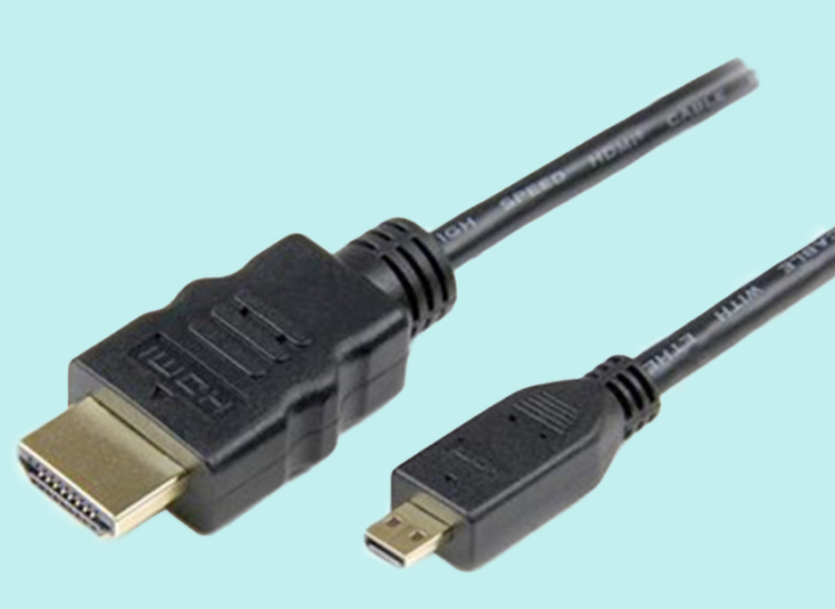
Sold units of the Raspberry PiThe Raspberry Pi is one of the best-selling British computers. As of December 2019, more than thirty million boards have been sold.Most Pis are made in a Sony factory in Pencoed, Wales, while others are made in China and Japan. Several generations of Raspberry Pis have been released. Raspberry Pi SBCs feature a Broadcom system on a chip (SoC) with an integrated ARM-compatible central processing unit (CPU) and on-chip graphics processing unit (GPU), while Raspberry Pi Pico has a RP2040 system on chip with an integrated ARM-compatible central processing unit (CPU).The first generation (Raspberry Pi Model B) was released in February 2012, followed by the simpler and cheaper Model A. In 2014, the Foundation released a board with an improved design, Raspberry Pi Model B+. These first generation boards feature ARM11 processors, are approximately credit-card sized and represent the standard mainline form-factor. Improved A+ and B+ models were released a year later.[clarification needed] A "Compute Module" was released in April 2014 for embedded applications.

The Raspberry Pi 2 was released in February 2015 and initially featured a 900 MHz 32-bit quad-core ARM Cortex-A7 processor with 1 GB RAM. Later versions featured a 1.2 GHz 64-bit quad-core ARM Cortex-A53 processor.[26]
A Raspberry Pi Zero with smaller size and reduced input/output (I/O) and general-purpose input/output (GPIO) capabilities was released in November 2015 for US$5. On 28 February 2017, the Raspberry Pi Zero W was launched, a version of the Zero with Wi-Fi and Bluetooth capabilities, for US$10.[27][28] On 12 January 2018, the Raspberry Pi Zero WH was launched, a version of the Zero W with pre-soldered GPIO headers.[29]
Raspberry Pi 3 Model B was released in February 2016 with a 1.2 GHz 64-bit quad core ARM Cortex-A53 processor, on-board 802.11n Wi-Fi, Bluetooth and USB boot capabilities.[30] On Pi Day 2018, the Raspberry Pi 3 Model B+ was launched with a faster 1.4 GHz processor, a three-times faster gigabit Ethernet (throughput limited to ca. 300 Mbit/s by the internal USB 2.0 connection), and 2.4 / 5 GHz dual-band 802.11ac Wi-Fi (100 Mbit/s).[31] Other features are Power over Ethernet (PoE) (with the add-on PoE HAT), USB boot and network boot (an SD card is no longer required).
Raspberry Pi 4 Model B was released in June 2019[2] with a 1.5 GHz 64-bit quad core ARM Cortex-A72 processor, on-board 802.11ac Wi-Fi, Bluetooth 5, full gigabit Ethernet (throughput not limited), two USB 2.0 ports, two USB 3.0 ports, and dual-monitor support via a pair of micro HDMI (HDMI Type D) ports for up to 4K resolution. The Pi 4 is also powered via a USB-C port, enabling additional power to be provided to downstream peripherals, when used with an appropriate PSU. The initial Raspberry Pi 4 board has a design flaw where third-party e-marked USB cables, such as those used on Apple MacBooks, incorrectly identify it and refuse to provide power.[32][33] Tom's Hardware tested 14 different cables and found that 11 of them turned on and powered the Pi without issue.[34] The design flaw was fixed in revision 1.2 of the board, released in late 2019.[35]
Raspberry Pi 400 Kit
Raspberry Pi 400 was released in November 2020. It features a custom board that is derived from the existing Raspberry Pi 4, specifically remodelled with a keyboard attached. A robust cooling solution similar to the one found in a Commodore 64 allows the Raspberry Pi 400's Broadcom BCM2711C0 processor to be clocked at 1.8 GHz, which is slightly higher than the Raspberry Pi 4 it's based on.[36] The keyboard-computer features 4 GB of LPDDR4 RAM.
Raspberry Pi Pico was released in January 2021 with a retail price of $4.[37] It was Raspberry Pi's first board based upon a single microcontroller chip; the RP2040, which was designed by Raspberry Pi in the UK.[38] The Pico has 264 KB of RAM and 2 MB of flash memory. It is programmable in MicroPython, CircuitPython, and C. It has partnered with Adafruit, Pimoroni, Arduino and Sparkfun to build Accessories for Raspberry Pi Pico and variety of other boards using RP2040 Silicon Platform.[39] Rather than perform the role of general purpose computer (like the others in the range) it is designed for physical computing, similar in concept to an Arduino[40]
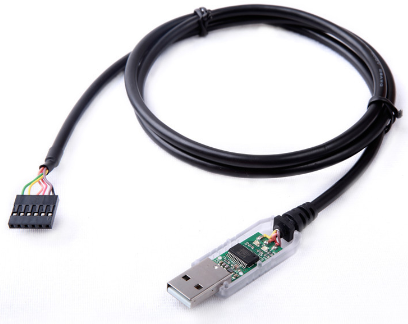
FTDI cable
The FTDI cable is a USB to Serial (TTL level) converter which allows for a simple way to connect TTL interface devices to USB.
The I/O pins of this FTDI cable are configured to operate at 5V.
The FTDI cable is designed around an FT232RQ, which is housed in a USB A connector.
![]()
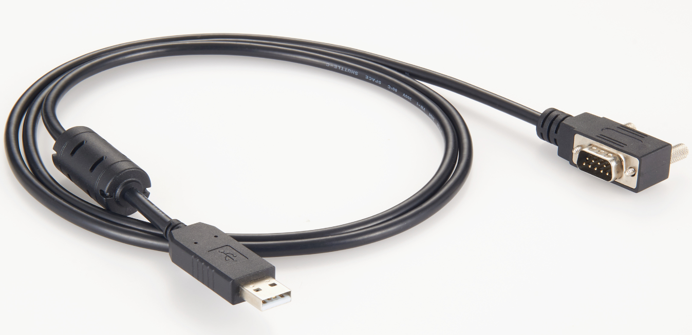
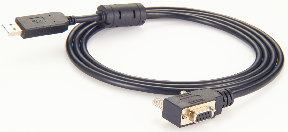
Sartorius Scale RS232 Cable
Adam Scale RS232 Cable
Adam Equipment RS232 To USB Adapter
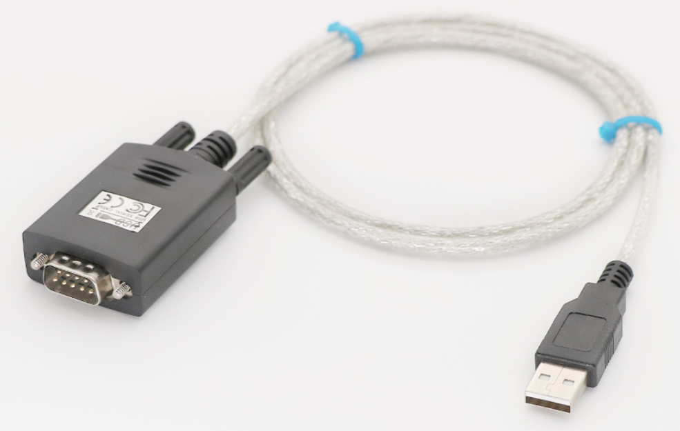
Scale and balance RS232 Cable
RS232 Data Cable For Scale
RS-232 Platform Scale Cable
RS-232 to USB Interface Cable
USB RS232 METTLER SCALE CABLE
RS232 Data Cable For SlimPRO Scale
USB Interface - RS232 to USB Connection
Precision Weighing Balance RS232 Cable
Adam Equipment RS-232 To USB Adapter
RS-232 to PC Cable for Adam GBK Bench Scale
USB cable for Brecknell 6700U series and CAS SW-RS series scale
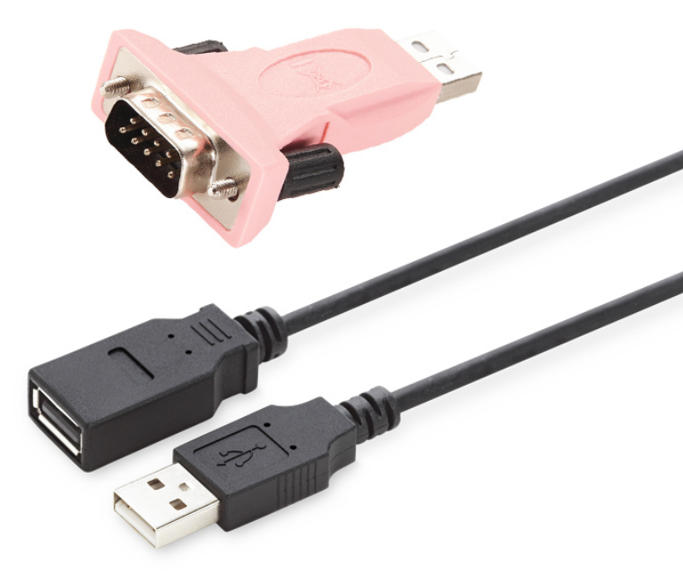
USB Cable for Temperature Humidity Data Logger
USB Cable is a 6in (152mm) cable used to connect the MA-46 Temperature and Humidity Data Logger docking station to a computer USB port. It is compatible with Windows 95, 98, 98ME, 2000, and XP, and is supplied with a CD with drivers for installation on PC.
Features:
Converts 9-pin plug to USB
Connects to RS232 cable
Included Items:
USB Cable
CD with Drivers
Laurel CBL02 USB-to-RS232 Adapter Cable
Connects the USB port of a PC to a Laureate meter with an RS232 option board
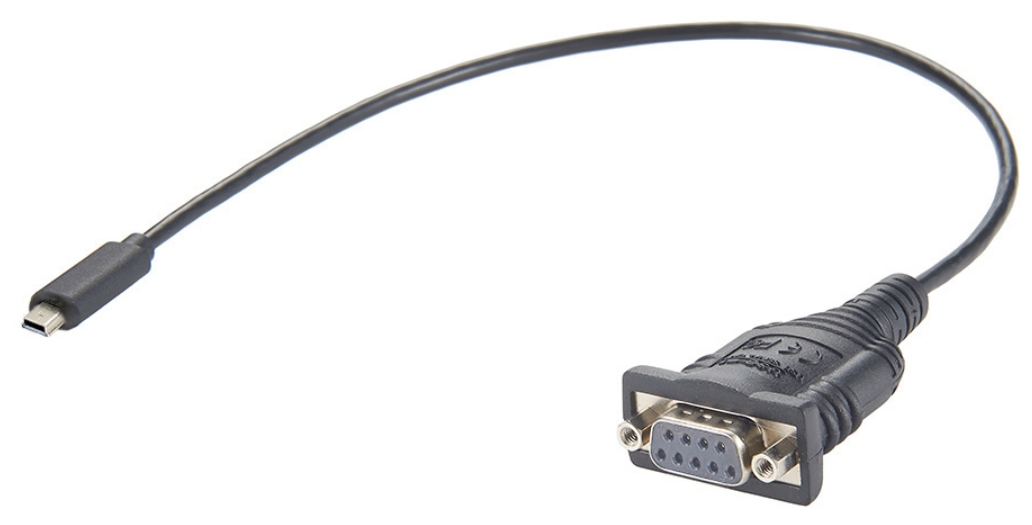
Data Cable mini USB RS232 9 pin
Data output Mini USB RS232 Cable
Sartorius 150404 Mini USB Cable RS232 9 Pin compatible
Data Cable Mini USB RS232 9Pin YCC03-D09 Sartorius compatible
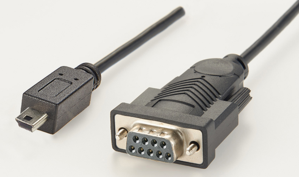
Data transfer to a printer or a computer is blocked when most common operating errors occur
LevelControl, an optoelectronic level monitoring helps prevent incorrect results from an unlevelled balance
Active monitoring of the USP minimum sample weight requirement
isoCAL helps prevent incorrect results due to an uncalibrated balance
Cal Audit Trail provides traceable documentation of all calibration and adjustment data inside the balance
GLP-compliant printouts with time and date stamps - with a Sartorius GLP printer YDP30
Password protection prevents unauthorised changes of weighing settings
Easy cleaning thanks to innovative housing design
Optimised draft ring and LevelControl ensure suitability for us in laminar airflow environments
The Mini-DVI connector is used on certain Apple computers as a digital alternative to the Mini-VGA connector. Its size is between the full-sized DVI and the tiny Micro-DVI. It is found on the 12-inch PowerBook G4 (except the original 12-inch 867 MHz PowerBook G4, which used Mini-VGA), the Intel-based iMac, the MacBook Intel-based laptop, the Intel-based Xserve, the 2009 Mac mini, and some late model eMacs.In October 2008, Apple announced the company was phasing Mini-DVI out in favor of Mini DisplayPort.Mini-DVI connectors on Apple hardware are capable of carrying DVI, VGA, or TV signals through the use of adapters, detected with EDID (Extended display identification data) via DDC. This connector is often used in place of a DVI connector in order to save physical space on devices. Mini-DVI does not support dual-link connections and hence cannot support resolutions higher than 1920×1200 @60 Hz.There are various types of Mini-DVI adapter:Apple Mini-DVI to VGA Adapter Apple part number M9320G/A (discontinued)Apple Mini-DVI to Video Adapter Apple part number M9319G/A, provided both S-Video and Composite video connectors (discontinued)Apple Mini-DVI to DVI Adapter (DVI-D) Apple part number M9321G/B (discontinued)Non-OEM Mini-DVI to HDMI adapters are also available at online stores such as eBay and Amazon, and from some retail stores, but were not sold by Apple.The physical connector is similar to Mini-VGA, but is differentiated by having four rows of pins arranged in two vertically stacked slots rather than the two rows of pins in the Mini-VGA.Connecting to a DVI-I connector requires a Mini-DVI to DVI-D cable plus a DVI-D to DVI-I adapter.
The Antenna Interface Standards Group (AISG) creates and maintains standards for the control and monitoring interface between a base station and a variety of tower-top equipment. These include antennas with remote electrical tilt (RET), tower mounted amplifiers and a variety of sensors that are used to monitor the operation of tower-top equipment.
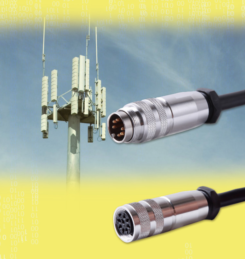
Remote Electrical Tilting device
Remote Electrical Tilt Unit for antenna with electrical down-tilt
Compliant to AISG 2.0 / 3GPP
Compact size( Light, Thin, Short, Small )
Suitable for operation under outdoor conditions
The Remote Electrical Tilt Unit (R.E.T.) allows for accurate control of antenna tilt eliminating site-access requirement, allowing the tilt to be adjusted remotely from the Base station/network control center and only in a matter of minutes. This allows for timely and accurate response to changing capacity requirements of the network. It can save your time, money and safety for the physical work access the sites.
The solution comprises of a Motor driven Antenna, with communication to the BTS and a microprocessor that controls the communication and performs supervisory functions. Most of the R.E.T. systems use the AISG protocol (Antenna Interface Standard Group) which is an open specifications for the control interface for these systems and SRT R.E.T. is compliant to AISA 2.0 / 3GPP.
RET (Remote electrical Tilt Unit)
Remote Control Unit(RCU)
Smart Bias Tee
DAS/RF COMPONENT